Blog

  • BC455 SCR274

    BC455 after restoration with aftermarket knob

    A little update

    This is the first actual blog post to the website. The others were older articles that i wrote up to a year ago.

    Article:

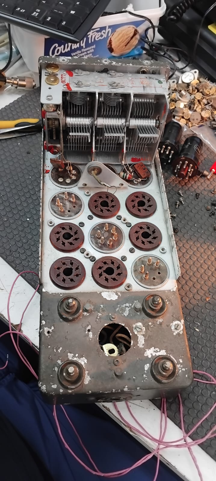
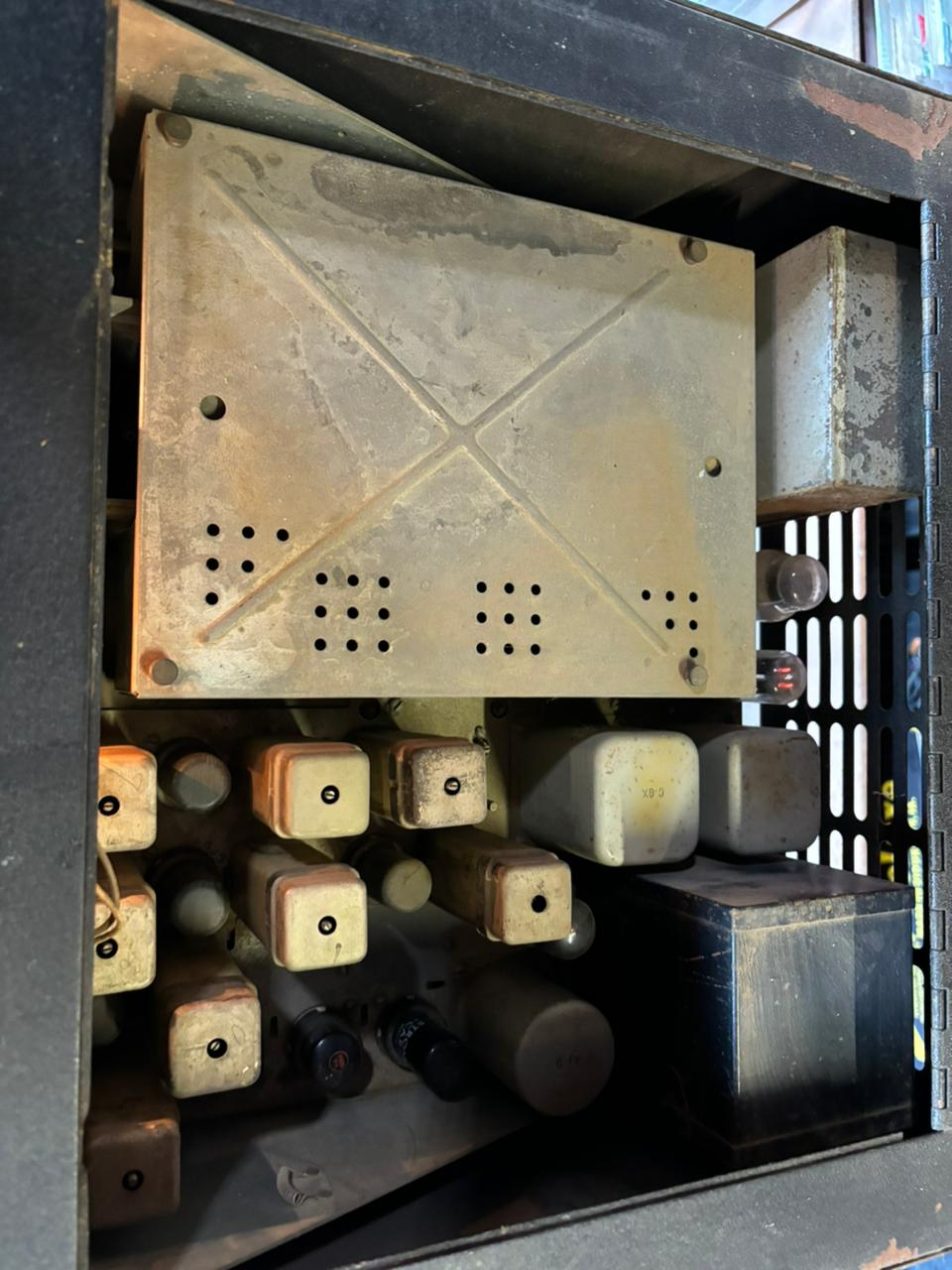
    I got this receiver a while back from a guy up north. I got this BC455, its accompanying transmitter, and a modulator unit for the transmitter. Those other two will be covered in a future post. They are all part of the SCR274 command set (also known as the ARC5 command set)

    When I received the radio it was in pretty decent condition compared to the other parts of the SCR274 set I have so far.

    I also got hold of dynamotor for the receiver (not the original type but still the correct voltage) from John ZS1WJ. That worked when i received it. I tested all the valves in the BC455 with my vintage valve tester and they all tested good. The BC455 had been re-wired to 12V on the filaments instead of 24V, which suited my dynamotor just fine since it also required 12V instead of 24V.

    Dynamotor Western electric PS-225

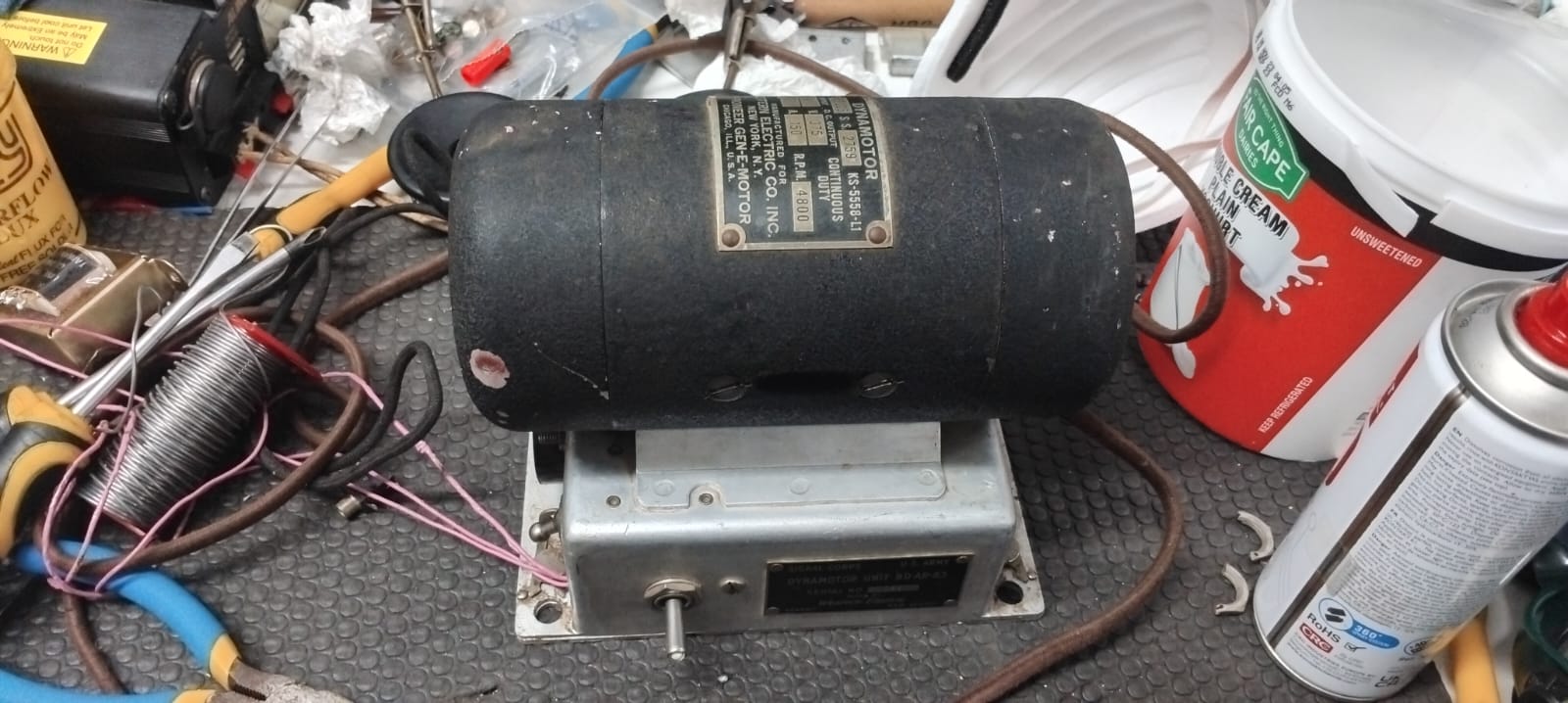
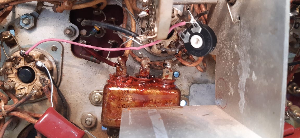
    I wired up the BC455 to the dynamotor and gave it power from my 13.8V 30A psu (13.8V is close enough to 12V that it works fine). Turns out that the dynamotor chassis is connected to +375V and the “HV out” is actually the ground of the dynamotor. This means that I gave the BC455 -375V which caused the smoothing capacitor inside to let the magic smoke out.

    A pool of “liquid” came out of the capacitor and went on the mat that i was working on. Later I found out that this was the highly toxic PCB oil (Polychlorinated Biphenyl oil). I wiped it up, clipped the lead that went to the capacitor so that I wouldn’t effect the operation of the rig. I then corrected the wiring of the rig so that there was +375V on the HV in on the receiver and the ground was actually grounded. I gave it power and hooked up a speaker to it and heard some noise.

    I then used my TinySA spectrum analyzer to generate a signal and feed it into the antenna input of the receiver. I tuned the signal in with the help of a oscilloscope on the audio output since the audio was extremely soft. It worked perfectly. I ended up replacing the audio transformer with a different one that gave much less distortion and more volume.

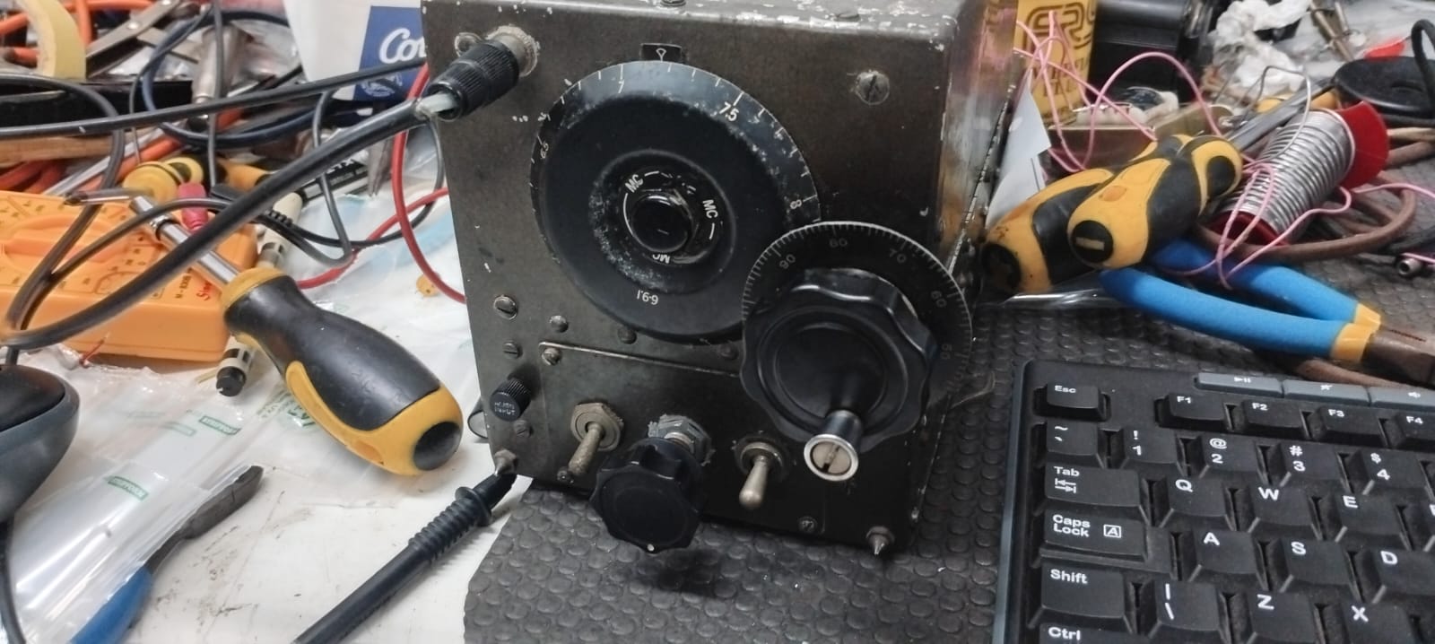
    There was one more issue: there was no way to add a knob to the since it was designed to be remote controlled via a wire that physically attached to the gearbox. I removed all the valves, the IF boxes and the gearbox to get to the back of the connector (both the valves and the if boxed are socket-ed which is great). I had to cut the connector bit off since it was screwed on and then two pins were put in so that it couldn’t unscrew. After I had done that I just added a knob and all worked well.

    The top is the chassis striped
  • FLDX400 and FRDX400 repair:

    I got this set of radios from Charl ZS1ZZ sometime near the end of 2024. They are all-vacuum tube radios from the 1960’s. They both somewhat worked when I plugged them into my current limiter, but not fully. The receiver (FRDX400) only received on some bands, and not very well on the ones that it did work on. The transmitter (FLDX400) didn’t work on any band but did turn on. I first gave both radios a thorough clean and sanded the rust off of the panels. I checked all the valves in both radio and they all looked fine. All of the valve filaments turned on in both radios. I then sprayed contact cleaner into all of the potentiometers and switched I could find on the radio. After cleaning the receiver all of the bands sprung back to life, but it still didn’t work very well. It wasn’t as sensitive as it was spec ’ed to be. I ran through the alignment procedure from the service manual and re-aligned the rf and if sections. It then worked perfectly on all bands and had a sensitivity of 0.5uV.

    I then had a look at the transmitter. I pulled out the finals and checked them for shorts. They were fine. I then measured the plate voltage on the finals and that was also good. Since the voltages on the finals looked OK, I started signal tracing the rig. I lost the signal after the 1st mixer. It took me ages to work out that the mixer balance potentiometer wasn’t making good contact. I had missed it with the contact cleaner earlier on when I was cleaning. I sprayed contact cleaner into and re-balanced the mixer and it started transmitting. I also performed a full alignment on the transmitter, and it works perfectly now.

    I plan for these radios to be paired with my linear amplifier when its all set up, or my fl-101 and fr-101 set (or possibly my ft901d), I am not quite sure yet.

  • Dim bulb current limiter

    What is a current limiter and what’s its purpose?

    A lighbulb current limiter is effectively a high-power resistor in series with the load. In this case the resistor is a lightbulb. The wattage of the lightbulb determines the maximum power that can be delivered to the load since they are in series. In my lightbulb current limiter, I also have a variac to vary the input AC voltage so that I can bring equipment up to operating voltage slowly for testing. The purpose of a lightbulb current limiter is for powering up equipment that is in an unknown state, especially valve equipment. For example, if you acquire an old valve psu, it is bd practice to just plug it into the wall and see what happens. If there is a problem on the secondary side of the transformer your brand new psu’s transformer could go up in smoke (ask me how I know).

    Required parts:

    • Incandescent lightbulbs (whatever wattage you want)
    • Sockets for those lightbulbs (screw of bayonet)
    • One switch per lightbulb (so that you can vary the amount of available power)
    • Power cable of sorts (or a 3 prong plug and some ac cable)
    • Wall socket (you will understand the purpose of this in the pictures)
    • Some sort of enclosure for all this
    • If you want to, also a variac
    Schematic of the dim bulb tester

    How to build it:

    • Mount the bulb sockets, the wall socket, and the switches to your enclosure
    • Mount the variac if you want to (it’s not required for the limiter to work)
    • Follow the schematic to wire it up
  • History of RADAR and the Cavity Magnetron

    RADAR

    During the late 19th century Heinrich Hertz ran experiments that showed that radio waves were reflected by metallic objects.

    Robert Watson-Watt, who was the supervisor of a National Radio Research Laboratory, was asked for his views on the discovery. He believed that radio waves could be bounced off aircraft to detect them. His assistant, Arnold Wilkins ran the calculations to determine the feasibility of detecting aircraft with radio waves.

    On 26 February 1935, they successfully demonstrated that it was indeed possible to detect aircraft using radio waves. They demonstrated this by using a BBC transmitter and picking up the reflections coming from a Handley Page Heyford bomber.

    In May 1935, they set up experiments which lead to the first working radar system. Six wooden towers were built, two transmitting towers and four receiving towers. After this success, 240ft wooden receiver towers and 360ft steel transmitter towers were built, and wires were hung between them to make curtain antennas. The wood was used to reduce secondary reflections that would make readings less accurate or create extra artifacts. This became the first Chain Home Radar station. By the start of WW2 there was a chain of radar stations in place around the coast of Britain. This system was in use all the way until 1953 when newer technology replaced it.

    Map of the chain home system

    Cavity magnetron

    What is a cavity magnetron? A cavity magnetron is a microwave source that uses tuned cavities to create an oscillation.

    The cavity magnetron was invented on 21 February 1940 by Sir John Randall and Harry Boot at the University of Birmingham, England. This first prototype produced 400w of power at a wavelength of 9.8cm. Before the invention of the Cavity magnetron came the Hull Magnetron invented by Albert W. Hull in 1920. This was a simpler design and might be discussed in a later article.

    In a cavity magnetron a DC voltage is applied between the centre cathode and the outer anode which, under a vacuum, allows electron emission from the cathode (there is a filament like any other vacuum tube that heats the cathode). These electrons fly past resonant cavities, which are part of the anode, at speeds that generate microwave energy. The microwaves are coupled out of the magnetron using an antenna and a wave guide. The resonant cavities act like LC circuits and determine the operating frequency of the magnetron.

    Function of a cavity magnetron

    The magnetron led to better radar systems with a higher resolution that were vehicle-portable. They allowed for easier navigation at night on aircraft and also meant that pilots could detect any enemy aircraft and see if they were in range of the aircraft’s guns. They have had many, many uses in our lives.

  • FT901D repair

    FT901D after repair

    I picked up a Yaesu FT-901D from Charl ZS1ZZ back in April. When I got it, it received well, but had no Tx. I feared the worst: blown final valves. The FT-901D is a hybrid set meaning that it has both transistors and valves in it. It has two 6146B’s as the final amplifier and a 12BY7A as a driver. 

    The first problem I found was that the valve filaments didn’t light. I found that if I wiggled the heater switch on the front of the radio a bit they would light. A bit of wd40 in the switch and it worked great. But still no transmit. 

    It took me a while to find but eventually I found the problem. He bias voltage on the 6146B’s is meant to be -110v in receive and -60v in transmit, but it stayed at -110v in transmit. This problem was traced to the rectifier C board which had a lifted trace on one of the transistors that triggered the rectifier B board to change the bias voltage to -60v in transmit. After I had fixed the broken trace the transmit came back to life, but a much-reduced power, only about 10w or so. It’s meant to kick out 100w easily. I also noticed that ssb, cw and am sounded very distorted, indicating a fluctuating power supply somewhere. 

    I then started measuring voltages on the finals. The screen grid voltage was dropping below 200v in transmit, and it was meant to be at around 245v in transmit. This was due to the screen grid supply sagging under an excessive current draw. Now I thought, what could cause excessive current draw on the screen grid of a valve? I couldn’t think of the answer, so I asked around. Greg ZS1IX helped me work out that the excessive current draw on the screen grid supply was caused by a drop in plate voltage during transmit. I measured the plate voltage and sure enough, the voltage was around 410v during transmit instead of the 845v its meant to be. This also explains the distorted ssb, am and cw in transmit, the voltage on the plate was unstable causing distortion on the output. 

    I then had to work out why the plate supply wasn’t at the correct voltage. I eventually dug out the rectifier A board which is the power supply board for the plate. The rectifier board was undamaged but the capacitor bank pcb underneath was cracked in half. I taped the two capacitors together back together and soldered them back to the rectifier A board and ran wires on the top of the rectifier A board in place of the broken traces. I plan on making a pcb to replace the cracked pcb, so this is a temporary solution. 

    There was one final problem: not all the digits on the digital display were lighting up. This was a simple fix, the led driver ic was partially blown. I fixed the blown part of the ic with a few bc547 transistors and some 4.7k resistors on the outside. This is also temporary; I need to get hold of the actual part. 

    It ain’t pretty but it works

    Finally, after all this work the transmit fired up perfectly and, after a tune-up, was kicking out a little over 100w! In the future I want to make that pcb board for the capacitor bank and do a full tune-up and alignment of the RF and IF sections, as well as align the power supply voltages of this transceiver. 

    A huge thanks to Greg ZS1IX for the help with troubleshooting this transceiver.

    Update:

    I sprayed WD-40 onto the band-switch contact for the driver board and the band-switch arced over causing carbon tracks to form on the wafers. I scraped the carbon off and flushed the contacts with Kontakt, but the damage was already done (by the way I really recommend Kontakt to anyone who works on radios) No power output on 40m.I began to investigate, at first I though the band switch was broken, so I checked every single contact related to 40m. This was quite a while after the band switch had arced over so I had forgotten that the arcing had happened on the driver section of the band switch. I soon discovered that all the contacts on the band switch were fine and that the problem was elsewhere.I then stated looking at the driver circuitry and soon found a resistor fried to a crisp on the trimmer C board. I replaced that resistor and 40m is back up, although only at 20W. No idea whats out of alignment to keep it down at 20W, but 20W is enough to drive my linear so its ok for now.

    Update again:

    I replaced the cracked pcb with a piece of acrylic and mounted everything to that.

    The new board

    TODO:

    I need new 6146B valves and a new 12BY7A driver, which are arriving in may.

  • AR-88 restoration

    A little history

    Inside the cabinet

    The AR-88 was a listening post receiver used during WW2 to listen to German radio communications. It was made by RCA for the war effort. The designers of the radio were told “to pull all the stops out” and the budget for the research and design for this radio was enormous. The result is a radio that is stable and is still more sensitive than a large amount of modern receivers. 

    The repair:

    The repair I did on my AR-88 was preventative maintenance (as well as adding the meter circuit). The first step was to get the nearly 50kg rig onto the floor and take it out of its case. It slides out on two rails which would have usually worked well except, thanks to the age of the rig, they were covered in rust and didn’t run smoothly. After I got the rig out of the case, I sprayed WD40 on the rails and cleaned the rust off which worked great. 

    I then put the radio onto my bench with the help of my parents and started cleaning it. After getting the dust off of it, I desoldered the wires going to the chokes and cleaned the leaking oil off of the chassis and chokes. The oil came from the chokes since when they had gotten hot, the oil inside had liquified and leaked out. This problem would be resolved later when I replaced the capacitors with better ones reducing the load on the choke. 

    After doing all the major cleaning I removed the knobs and the front panel and cleaned it up with Handy Andy and soapy water (be careful with leaving the Handy Andy on for too long, it can damage the paint!). While carrying the front panel back to the garage I fell down the stairs and the mechanical dial lock broke as I dropped the roughly 10kg steel plate on the floor (it’s about a cm thick). The front panel wasn’t damaged besides the dial lock screw which I am going to re-make on a lathe when I get access to one. 

    After the cleaning process, I started work on replacing old degrading components (the radio is around 80 years old and so are the components). I replaced the PCB-filled tub capacitors (PCB oil is carcinogenic and the seals on the capacitor tubs are rubber and have degraded and leak). There are six of them in the AR-88 all of which have to be replaced. It is EXTREMELY important to wear gloves while handling them. There is another oil-filled capacitor bank which I left in there because it was in great condition and wasn’t leaking (and wasn’t full of PCB oil). I replaced the tub capacitors with foil capacitors which worked great. The filament voltage dropping resistors (100ohms and 150ohms at 10w) were corroded and were replaced. A few resistors and micamold capacitors (cheaper, slightly worse mica capacitors) around the rig replaced. There is a capacitor that couples the audio out of the audio output section into the audio transformer. If this capacitor fails as a short, it puts B+ on one side of the transformer and ground on the other side blowing up the rare audio transformer. It’s extremely important to replace. 

    Bathtub Capacitor

    After having replaced all the old components that were degrading or prone to failure, I started work on the meter circuit. During war time production, there was a shortage of signal strength meters and as a result they just put a cover over the hole where the meter went. My AR-88 came with a meter installed and the wiring for the meter in the lacing, but both sides of the meter grounded. I still haven’t found out why since the wiring and meter are definitely factory original, but the rest of the meter circuitry wasn’t there (a potentiometer, a resistor and a capacitor). I have no idea how this happened… 

    After installing the meter and calibrating it by getting the needle all the way to the left with the antenna input shorted (the meter’s mechanical zero set to the right instead of the normal left). I then performed a full alignment. 

    The electrical restoration is complete and all that needs to be done is to re-machine the dial lock knob and paint it.