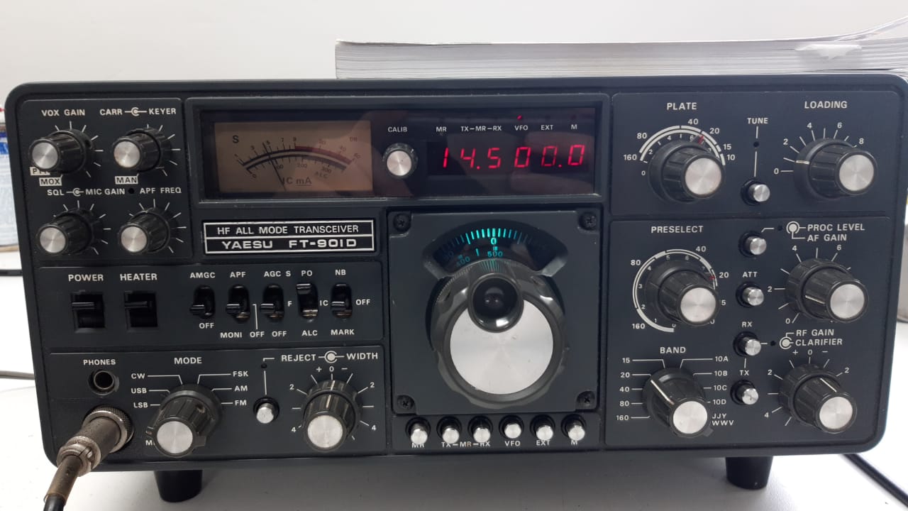
I picked up a Yaesu FT-901D from Charl ZS1ZZ back in April. When I got it, it received well, but had no Tx. I feared the worst: blown final valves. The FT-901D is a hybrid set meaning that it has both transistors and valves in it. It has two 6146B’s as the final amplifier and a 12BY7A as a driver.
The first problem I found was that the valve filaments didn’t light. I found that if I wiggled the heater switch on the front of the radio a bit they would light. A bit of wd40 in the switch and it worked great. But still no transmit.
It took me a while to find but eventually I found the problem. He bias voltage on the 6146B’s is meant to be -110v in receive and -60v in transmit, but it stayed at -110v in transmit. This problem was traced to the rectifier C board which had a lifted trace on one of the transistors that triggered the rectifier B board to change the bias voltage to -60v in transmit. After I had fixed the broken trace the transmit came back to life, but a much-reduced power, only about 10w or so. It’s meant to kick out 100w easily. I also noticed that ssb, cw and am sounded very distorted, indicating a fluctuating power supply somewhere.
I then started measuring voltages on the finals. The screen grid voltage was dropping below 200v in transmit, and it was meant to be at around 245v in transmit. This was due to the screen grid supply sagging under an excessive current draw. Now I thought, what could cause excessive current draw on the screen grid of a valve? I couldn’t think of the answer, so I asked around. Greg ZS1IX helped me work out that the excessive current draw on the screen grid supply was caused by a drop in plate voltage during transmit. I measured the plate voltage and sure enough, the voltage was around 410v during transmit instead of the 845v its meant to be. This also explains the distorted ssb, am and cw in transmit, the voltage on the plate was unstable causing distortion on the output.
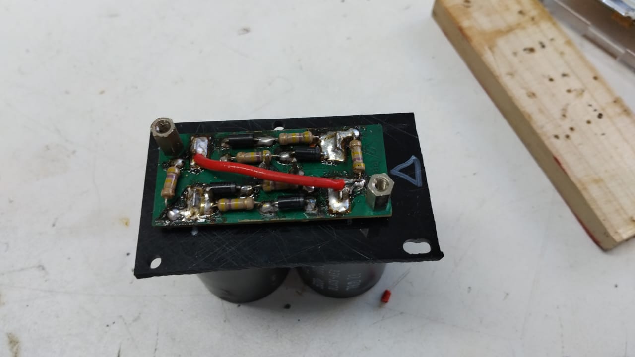
I then had to work out why the plate supply wasn’t at the correct voltage. I eventually dug out the rectifier A board which is the power supply board for the plate. The rectifier board was undamaged but the capacitor bank pcb underneath was cracked in half. I taped the two capacitors together back together and soldered them back to the rectifier A board and ran wires on the top of the rectifier A board in place of the broken traces. I plan on making a pcb to replace the cracked pcb, so this is a temporary solution.
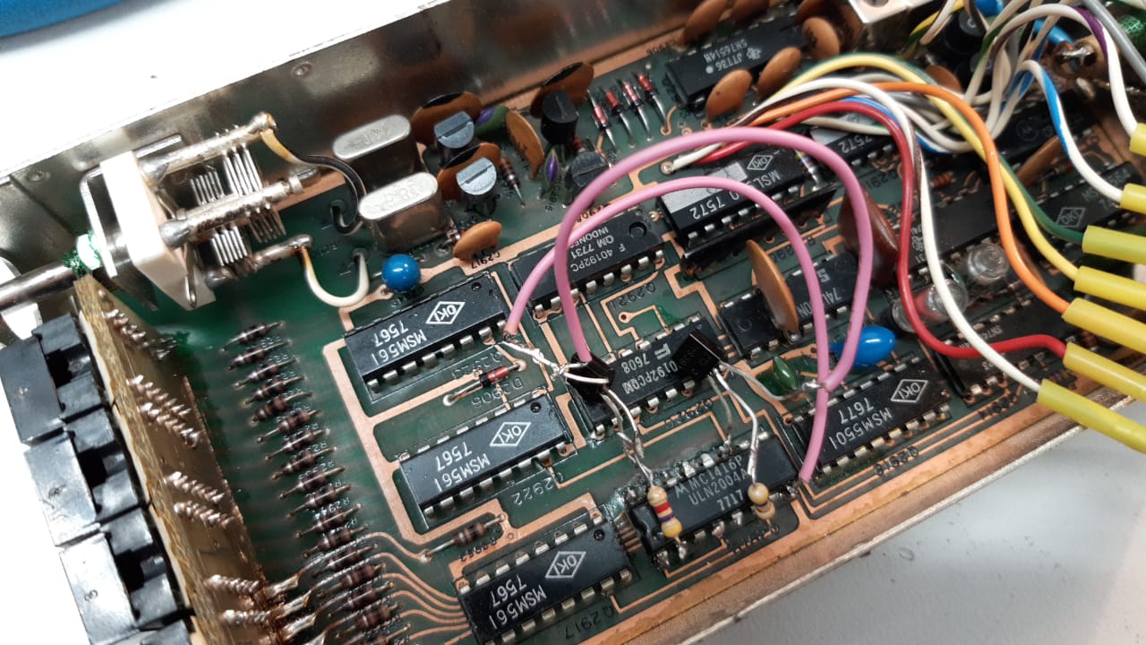
There was one final problem: not all the digits on the digital display were lighting up. This was a simple fix, the led driver ic was partially blown. I fixed the blown part of the ic with a few bc547 transistors and some 4.7k resistors on the outside. This is also temporary; I need to get hold of the actual part.
Finally, after all this work the transmit fired up perfectly and, after a tune-up, was kicking out a little over 100w! In the future I want to make that pcb board for the capacitor bank and do a full tune-up and alignment of the RF and IF sections, as well as align the power supply voltages of this transceiver.
A huge thanks to Greg ZS1IX for the help with troubleshooting this transceiver.
Update:
I sprayed WD-40 onto the band-switch contact for the driver board and the band-switch arced over causing carbon tracks to form on the wafers. I scraped the carbon off and flushed the contacts with Kontakt, but the damage was already done (by the way I really recommend Kontakt to anyone who works on radios) No power output on 40m.I began to investigate, at first I though the band switch was broken, so I checked every single contact related to 40m. This was quite a while after the band switch had arced over so I had forgotten that the arcing had happened on the driver section of the band switch. I soon discovered that all the contacts on the band switch were fine and that the problem was elsewhere.I then stated looking at the driver circuitry and soon found a resistor fried to a crisp on the trimmer C board. I replaced that resistor and 40m is back up, although only at 20W. No idea whats out of alignment to keep it down at 20W, but 20W is enough to drive my linear so its ok for now.
Update again:
I replaced the cracked pcb with a piece of acrylic and mounted everything to that.
TODO:
I need new 6146B valves and a new 12BY7A driver, which are arriving in may.